技術情報
M5Stack Basicで通信機能付き心拍・血中酸素モニタを作る
2020.04.28

コロナウィルスの蔓延により、医療崩壊や軽度感染者の自宅待機が新たな問題を引き起こしてきています(2020年4月26日現在)。なぜ、助けを呼べなかったのか?なぜ、周りの人達は異変に気付かなかったのだろうか?おそらく、人との接触を避ける今、病状が急変した時には取り返しのつかない状態になっているのだと思います。
世の中には、パルスオキシメーター(心拍・血中酸素モニタ)はありますが、家庭用で使うものには、変化を通知するための通信機能がありません。
そこで、軽度感染者の変化にいろんな人が気付けるよう、身の回りに転がっているIoT部品で通信機能付きパルスオキシメーターを作ってみました。

用意するもの
身の回りにないかもしれませんが、下記を用意してください。
M5Stack Basic
LCD表示必要なければArduino Nano等でも大丈夫です。
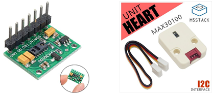
パルス酸素濃度計および心拍数センサーIC(MAX3010x)
私は、GAOHOU(中国製)のMAX30100開発ボードセンサを購入しましたが、Groveコネクタで接続可能なM5Stack用心拍センサユニットの方が便利かもしれません。
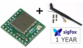
Sigfox Breakout board(BRKWS01)
BRKWS01はSigfox Devkitとして1年間の無料通信回線※1 込みでお使いいただけます。
※1 2022年7月1日をもって、Devkit対応デバイスのDevkit登録(無償回線利用)が終了いたしました。
Sigfox回線をご利用の際には、Sigfox Buyにて有償回線をご購入ください。
Sigfox Buy お申込みからご利用開始までの流れはこちら
他の通信モジュールを使っても結構です。今回は、こちら(M5Stack BasicでSigfox RFモニタを作る)で作ったプロトタイプをベースにパルスオキシメーターを追加していきます。
MAX3010xとM5Stackを接続する
心拍センサMAX3010xとM5Stackとは、I2Cで接続することとなります。
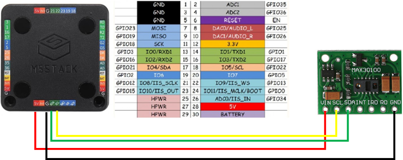
MAX30100のVinをM5Stackの5V出力端子に、GNDをGNDに、SCLとSDAはそのまま、M5Stack側のSCL、SDAに接続します。
Sigfoxモジュールとの接続はシリアル(Serial2)用のG16,17がそのまま使えます。
MAX3010x用プログラム
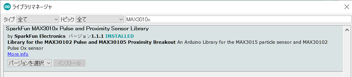
MAX3010x用ライブラリのインストール
Arduino IDEのライブラリマネージャ([ツール]_[ライブラリを管理]メニュー)からSparkFun MAX3010x Pulse and Proximity Sensor Libraryをインストールします。
ソースコード
下記の通りとなります。
#include
#include
#include "MAX30105.h"
#include "spo2_algorithm.h"
#include "xbm.h" //my bitmap

MAX30105 particleSensor;

uint32_t irBuffer[50]; //infrared LED sensor data
uint32_t redBuffer[50];  //red LED sensor data

int32_t bufferLength; //data length
int32_t spo2; //SPO2 value
int8_t validSPO2; //indicator to show if the SPO2 calculation is valid
int32_t heartRate; //heart rate value
int8_t validHeartRate; //indicator to show if the heart rate calculation is valid

bool doStart = false; // flag true if sensing should be started

void setup()
{
  Serial.begin(115200); // to PC via USB
  Serial2.begin(9600, SERIAL_8N1, 16, 17);   // to Sigfox module

  M5.begin();
  M5.Power.begin();
  M5.Lcd.clear(BLACK);
  M5.Lcd.setTextSize(2);

  // Initialize sensor
  if (!particleSensor.begin(Wire, I2C_SPEED_FAST)) //Use default I2C port, 400kHz speed
  {
    M5.Lcd.setTextColor(RED);
    M5.Lcd.println("MAX30105 was not found. Please check wiring/power.");
    while (1);
  }

  M5.Lcd.setTextColor(BLUE);
  M5.Lcd.println("A: start measuring");
  M5.Lcd.println("C: send message");
}

void loop()
{
  M5.update();  //update button state
  if (doStart) {
    startSense();
  }
  if (M5.BtnA.wasReleased()) {
    doStart = true;
  }
}

void startSense()
{
  byte ledBrightness = 55; //Options: 0=Off to 255=50mA
  byte sampleAverage = 4; //Options: 1, 2, 4, 8, 16, 32
  byte ledMode = 2; //Options: 1 = Red only, 2 = Red + IR, 3 = Red + IR + Green
  byte sampleRate = 200; //Options: 50, 100, 200, 400, 800, 1000, 1600, 3200
  int pulseWidth = 411; //Options: 69, 118, 215, 411
  int adcRange = 4096; //Options: 2048, 4096, 8192, 16384

  particleSensor.setup(ledBrightness, sampleAverage, ledMode, sampleRate, pulseWidth, adcRange); //Configure sensor with these settings

  bufferLength = 50; //buffer length of 50 stores 4 seconds of samples running at 25sps

  //read the first 50 samples, and determine the signal range
  for (byte i = 0 ; i < bufferLength ; i++)
  {
    while (particleSensor.available() == false) //do we have new data?
      particleSensor.check(); //Check the sensor for new data

    redBuffer[i] = particleSensor.getRed();
    irBuffer[i] = particleSensor.getIR();
    particleSensor.nextSample(); //We're finished with this sample so move to next sample

    Serial.print("red="); Serial.print(redBuffer[i], DEC);
    Serial.print(", ir=");  Serial.println(irBuffer[i], DEC);
  }

  //calculate heart rate and SpO2 after first 50 samples (first 4 seconds of samples)
  maxim_heart_rate_and_oxygen_saturation(irBuffer, bufferLength, redBuffer, &spo2, &validSPO2, &heartRate, &validHeartRate);

  //Continuously taking samples from MAX30102. Heart rate and SpO2 are calculated every 1 second
  while (1)
  {
    //dumping the first 25 sets of samples in the memory and shift the last 75 sets of samples to the top
    for (byte i = 25; i < bufferLength; i++)
    {
      redBuffer[i - 25] = redBuffer[i];
      irBuffer[i - 25] = irBuffer[i];
    }

    //take 25 sets of samples before calculating the heart rate.
    for (byte i = 25; i < bufferLength; i++)
    {
      while (particleSensor.available() == false) //do we have new data?
        particleSensor.check(); //Check the sensor for new data

      redBuffer[i] = particleSensor.getRed();
      irBuffer[i] = particleSensor.getIR();
      particleSensor.nextSample(); //We're finished with this sample so move to next sample

      //send samples and calculation result to terminal program through UART
      Serial.print("red="); Serial.print(redBuffer[i], DEC);
      Serial.print(", ir=");  Serial.print(irBuffer[i], DEC);

      Serial.print(", HR="); Serial.print(heartRate, DEC);
      Serial.print(", HRvalid="); Serial.print(validHeartRate, DEC);
      Serial.print(", SPO2="); Serial.print(spo2, DEC);
      Serial.print(", SPO2Valid="); Serial.println(validSPO2, DEC);

      checkButton();
    }

    maxim_heart_rate_and_oxygen_saturation(irBuffer, bufferLength, redBuffer, &spo2, &validSPO2, &heartRate, &validHeartRate);
    printToDisplay();
  }
}

void printToDisplay()
{
  //M5.Lcd.clear(BLACK);
  M5.Lcd.fillScreen(TFT_BLACK);
  M5.Lcd.setTextColor(WHITE);
  M5.Lcd.setTextSize(4);
  //M5.Lcd.setCursor(0,0);
  if(validSPO2 && validHeartRate) {
    M5.Lcd.drawXBitmap(0, 5, hb2_bmp, 64, 32, TFT_RED);
    M5.Lcd.setCursor(0,60);
    M5.Lcd.print("HR: "); M5.Lcd.println(heartRate, DEC);
    M5.Lcd.print("SPO2: "); M5.Lcd.println(spo2, DEC);
  } else {
    M5.Lcd.drawXBitmap(0, 5, hb1_bmp, 64, 32, TFT_WHITE);
    M5.Lcd.setCursor(0,60);
    M5.Lcd.print("Not valid");
  }
}

void checkButton()
{
  M5.update();
  if (M5.BtnC.wasReleased()) {
    sendSigfoxMessage();
  }
}

void sendSigfoxMessage()
{
  if(validSPO2 && validHeartRate) {
    String msg = "AT$SF=" + String(heartRate, HEX) + String(spo2, HEX);
    Serial2.println(msg);
    M5.Lcd.println(msg);
    delay(10000);
  }
}
startSense()関数内がPulse Oximeterセンサ処理部分になります。
getRed()、getIR()メソッドで、赤色光(R)と赤外光(IR)の値を取得し、maxim_heart_rate_and_oxygen_saturation関数内でR / IRの比率により、heartRate(心拍)とspo2(血中酸素)を計算してくれます。
赤色光(R)を血液に当てると、ヘモグロビンと酸素がより多く結びついている場合、多くの光が指を通り抜けるそうです。逆に赤外光(IR)は酸素との結びつきに係わらず、血液を通り抜けるため、R / IR比率を調べることにより、血中酸素量をセンシングできます。
コニカミノルタさんのページにパルスオキシメーターの原理が分かりやすく解説されています。
M5Stack上にビットマップ表示
画面上に心拍(HeartRate)と血中酸素(SpO2)を表示するだけでは味気ないので、測定中を表す画像を表示してみます。
M5Stackでは、SDカードに保存した画像ファイルを読み込み表示する方法の他に、1ドットを1ビットで表した配列データ(XBitMap[XBM])をLCD表示する方法もあります。drawXBitmap関数に画像配置左上座標(x,y)と画像サイズ(width, height)、塗りつぶしする色(color)に加え、XBitMap配列データを渡します。
M5.Lcd.drawXBitmap(int16_t x, int16_t y, const uint8_t *bitmap, int16_t width, int16_t height, uint16_t color)
XBitMapの作成方法
お手持ちの画像ファイルをConvert Image to XBMサイトでXBMに変換できます。変換された配列は、
static char xxx_bits[] = {
  0x00, 0x00, 0x00, (中略), 0x00, 0x00, 0x00,
  };
といった形でダウンロードできますので、その配列をdrawXBitmap関数に渡すこととなります。今回のソースコードでは、xbm.hファイルに配列データを書いています。
ちなみに、今回は、こんな![]() と
と![]() 画像を用意しました。
画像を用意しました。
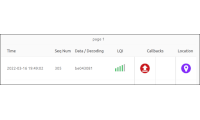
心拍・血中酸素をSigfoxで送信する
取得した心拍(HeartRate)、血中酸素(SpO2)をsendSigfoxMessage関数内でデータ送信しています。AT$SFコマンドでメッセージ送信をしているだけですので、細かい説明は割愛します。
本当は、血中酸素濃度が一定の値を下回ったらメッセージ送信するという仕組みにすれば、もう少し実用っぽいプログラムになるかもしれませんが。
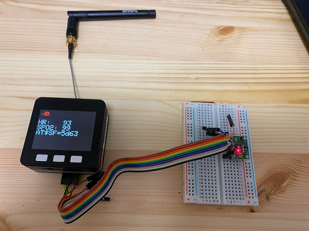
動作確認
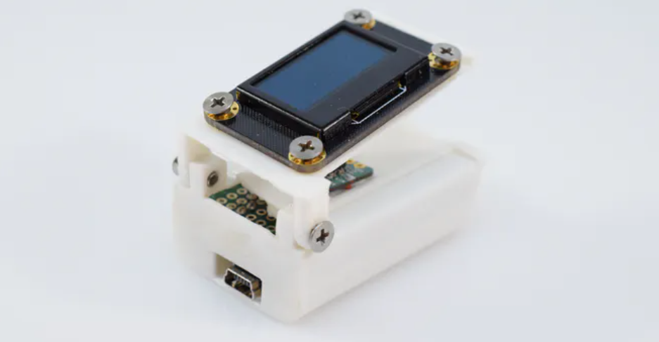
指をMAX30100の赤く光っている部分に当て、Aボタンを押せばセンシングが開始されます。数秒後に結果が画面上に表示されます。Cボタンを押せば、その結果をSigfoxメッセージとして送信します。
反省点
今回、MAX3010xの開発用ボードをそのまま使ったため、測定時に指がセンサ部に接触してしまい有効値を取得するのに苦労しました。直接センサ部に触れてはだめだし、離れすぎてもだめ。
3Dプリンタがあれば、Arduino Project Hubのサンプルのように指が安定するようなものができるのでしょうが。。。